

Smart Health Monitor Device | Heart Rate & Smart Blood Oxygen Monitor With Automatic Data Saving System
Hello and Welcome to Freaky Diodes again here we are back with another great electronics project for this pandemic situation. As we all know there are lots of Health checks devices which can easily monitor our Oxygen & Heart Rate. So, we came with a DIY Heart Rate & Smart Blood Oxygen Monitor with Smart Data Saving System.
Also Read: Heart Rate Monitor Using Arduino
About the Smart Health Monitor Device Project :
In this Project, We had made a Smart Health Monitoring Device that can measure SpO2 level & heart rates. This project is based on Ardruino and this device can be connected to an android app that automatically saves the sensor data in a text file.
Also Read: Electronic Mosquito Repellent
Components Required For Smart Health Monitor Device –
You can easily get all the components from Amazon easily. All the links are given.
| Components | Buy From Amazon |
|---|---|
| Max30100 sensor | Buy Now |
| Any Ardruino Board(Uno, Nano) | Buy Now |
| OLED Display (SSD 1306) | Buy Now |
| Bluetooth HC 05 | Buy Now |
| Wires | Buy Now |
Program Code for Smart Health Monitor Device :
Also Read: Smart Gesture Controlled Switch Using Arduino
- First we need to install the Arduino IDE and install the required libraries.
- Now go to tools section and click on the library manager.
- And, Search the mentioned libraries – [“Addafurit GFX”, “Oak Oled”, “Max 30100”] then install these libraries.
- After installing all the libraries, we need to include the required libraries in the code first.
#include <Wire.h>
#include "MAX30100_PulseOximeter.h"

#include "Wire.h"
#include "Adafruit_GFX.h"
#include "OakOLED.h"
#define REPORTING_PERIOD_MS     1000
OakOLED oled;
// PulseOximeter is the higher level interface to the sensor
// it offers:
//  * beat detection reporting
//  * heart rate calculation
//  * SpO2 (oxidation level) calculation
PulseOximeter pox;

uint32_t tsLastReport = 0;
- After including all the libraries, we will add a short Bitmap code which has a heart symbol logo. This function will displays the heart bitmap logo whenever the heart beats.
const unsigned char bitmap [] PROGMEM=
{
 0x00, 0x00, 0x00, 0x00, 0x01, 0x80, 0x18, 0x00, 0x0f, 0xe0, 0x7f, 0x00, 0x3f, 0xf9, 0xff, 0xc0,
 0x7f, 0xf9, 0xff, 0xc0, 0x7f, 0xff, 0xff, 0xe0, 0x7f, 0xff, 0xff, 0xe0, 0xff, 0xff, 0xff, 0xf0,
  0xff, 0xf7, 0xff, 0xf0, 0xff, 0xe7, 0xff, 0xf0, 0xff, 0xe7, 0xff, 0xf0, 0x7f, 0xdb, 0xff, 0xe0,
  0x7f, 0x9b, 0xff, 0xe0, 0x00, 0x3b, 0xc0, 0x00, 0x3f, 0xf9, 0x9f, 0xc0, 0x3f, 0xfd, 0xbf, 0xc0,
  0x1f, 0xfd, 0xbf, 0x80, 0x0f, 0xfd, 0x7f, 0x00, 0x07, 0xfe, 0x7e, 0x00, 0x03, 0xfe, 0xfc, 0x00,
  0x01, 0xff, 0xf8, 0x00, 0x00, 0xff, 0xf0, 0x00, 0x00, 0x7f, 0xe0, 0x00, 0x00, 0x3f, 0xc0, 0x00,
  0x00, 0x0f, 0x00, 0x00, 0x00, 0x06, 0x00, 0x00, 0x00, 0x00, 0x00, 0x00, 0x00, 0x00, 0x00, 0x00
};- Now, we will make a setup function & set the Bluetooth baud rate and other settings.
// Callback (registered below) fired when a pulse is detected
void onBeatDetected()
{
    Serial.println("Beat!");
    oled.drawBitmap( 60, 20, bitmap, 28, 28, 1);
    oled.display();
}

void setup()
{
    Serial.begin(9600);

oled.begin();
oled.clearDisplay();
  oled.setTextSize(1);
  oled.setTextColor(1);
  oled.setCursor(0, 0);

  oled.println("Initializing pulse oximeter..");
oled.display();
Serial.print("Initializing pulse oximeter..");- Code for Showing Sensor Status –
// Initialize the PulseOximeter instance
    // Failures are generally due to an improper I2C wiring, missing power supply
    // or wrong target chip
    if (!pox.begin()) {
        Serial.println("FAILED");
        oled.clearDisplay();
        oled.setTextSize(1);
        oled.setTextColor(1);
        oled.setCursor(0, 0);
        oled.println("FAILED");
        oled.display();
        for(;;);
    } else {
      oled.clearDisplay();
        oled.setTextSize(1);
        oled.setTextColor(1);
        oled.setCursor(0, 0);
        oled.println("SUCCESS");
         oled.display();
        Serial.println("SUCCESS");
}- Now we will create a function in loop which will updates & displays the sensor readings on the OLED screen.
// The default current for the IR LED is 50mA and it could be changed
    //   by uncommenting the following line. Check MAX30100_Registers.h for all the
    //   available options.
    // pox.setIRLedCurrent(MAX30100_LED_CURR_7_6MA);

    // Register a callback for the beat detection
    pox.setOnBeatDetectedCallback(onBeatDetected);
}

void loop()
{
    // Make sure to call update as fast as possible
    pox.update();

    // Asynchronously dump heart rate and oxidation levels to the serial
    // For both, a value of 0 means "invalid"
    if (millis() - tsLastReport > REPORTING_PERIOD_MS) {
        Serial.print("Heart Bpm");
        Serial.print(pox.getHeartRate());
        Serial.print("-----");
        Serial.print("Oxygen percent");
        Serial.print(pox.getSpO2());
        Serial.println("\n");
        oled.clearDisplay();
        oled.setTextSize(1);
        oled.setTextColor(1);
        oled.setCursor(0,16);
        oled.println(pox.getHeartRate());


        oled.setTextSize(1);
        oled.setTextColor(1);
        oled.setCursor(0, 0);
        oled.println("Heart Bpm");

        oled.setTextSize(1);
        oled.setTextColor(1);
        oled.setCursor(0, 30);
        oled.println("Spo2");

        oled.setTextSize(1);
        oled.setTextColor(1);
        oled.setCursor(0,45);
        oled.println(pox.getSpO2());
        oled.display();
        tsLastReport = millis();
    }
}
Connections of Smart Health Monitor Device :
- Connect the 5V Ardruino pin to OLED & MAX30100 VCC pin.
- Connect the GND of Ardruino to OLED & MAX30100 GND pin.
- Connect the SCL of Ardruino to SCL OLED & MAX30100 pin.
- Connect the SDA of Ardruino to SDA OLED & MAX30100 pin.
- Connect the 5V of Ardruino to Bluetooth VCC pin.
- Connect the GND of Ardruino to Bluetooth GND pin.
- Connect the RX to TX and TX to RX.
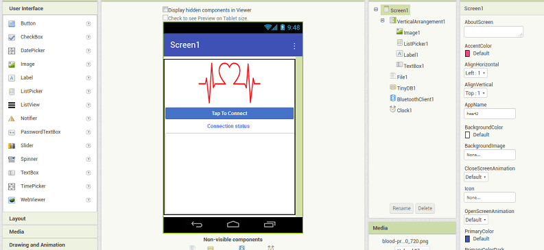
Android App For Data Saving:
We will build a app to store the Monitored Data into a Text file. We will us MIT App Invertor to build the app. MIT App Inverted is easy to use and simulate.
First create a layout and add the following components :
- A Button
- An Image View
- A Text Input
- A Text level
- Bluetooth Clint
- File Storage
- Clock Timmer
Now Join the MIT App Invertor Code according to the figure below :
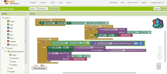
Download the Source Code & App Apk – Click Here
Working of Smart Health Monitor Device –
After Installing the code and connecting all the components we will test the working of Smart Heath Monitor Device –
- First of all, Power on the Ardruino.
- After powering on the OLED screen will shows a message – “Initializing Sensor.”
- After a couple of seconds Arduino detects the sensor, shows the reading of sensor. Initially, it will show 0 or false.
- Now place your finger on the sensor and it will take few seconds to detect the heartbeat rate & SPO2 (blood oxygen level).
- The Heartbeat rate & SpO2 (oxygen percentage in the blood) will be displayed on the OLED screen.
- Now open the App and connect it through Bluetooth.
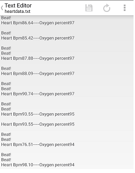
- After connecting the app, the SpO2 and pulse rate will display on the app.
- And the app will automatically saved the Oxygen & Heart rate in a text file.
For more electronics projects visit our website regularly and don’t forget to join our social media groups for the latest updates of jobs, internships & projects.


