
")
Welcome back freaks, We are back with another awesome electronics project. In this project we have made a Heart Rate Monitor using Arduino which can monitor your heart rate i.e. speed of heartbeat. And, it will be also monitor the body temperature, heart beat rate and blood pressure in order to keep us healthy.
Also Read: Wireless AC light Dimmer Using Arduino: Hand Gesture based
About the Heart Rate Monitor Using Arduino:
In this project, we have made a heart rate monitor using Arduino and a heartbeat sensor. To measure the body temperature we have used thermometers and for blood pressure, we used a Sphygmomanometer. Basically, there are two ways to measure the heart rate, one is manually and the other is using a heart rate sensor. We have used a heart rate sensor in this project.
What is Heartbeat Sensor?
A heartbeat sensor is a device or senor which is used to measure the heart hate, measuring heart beat using this sensor is very easy. This sensor comes in different shapes and sizes and allows us instantly to measure the heartbeat. The Heartbeat Sensors are available in Smart Watches, Smart Phones, smart bands, etc. It measure the heartbeat in bpm, bpm indicates the number of times the heart is expanding in one minute.
Also Read: Social Distancing Cap Using Arduino
The heartbeat sensor uses the principle of Photoplethysmograph. According to Photoplethysmopgraph, the changes in the intensity of the light passing through any organ measure the changes in the volume of blood that organ.
A simple heartbeat sensor includes a sensor that consists an IR LED & a Photodiode. And a control circuit that includes an Op-amp IC.
Components Required for Heart Rate Monitor Using Arduino:
| Components | Buy From Amazon |
|---|---|
| Arduino Uno | Buy Now |
| 16 x 2 LCD Display | Buy Now |
| Heartbeat Sensor Module with Probe | Buy Now |
| Mini Breadboard | Buy Now |
| Push Button | Buy Now |
| 10KΩ Potentiometer | Buy Now |
| 330Ω Resistor | Buy Now |
| Connecting Wires | Buy Now |
Circuit Diagram of Heart Rate Monitor Using Arduino:
The heartbeat sensor has a clip to scan the fingerprint and three pins VCC, GND and the Data for connecting.
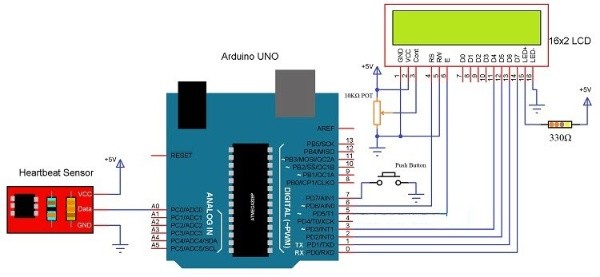
The circuit diagram of Heart Rate monitor using Arduino and heartbeat sensor is quite simple. To display the heartbeat rate a 16 x 2 LCD display is connect with Arduino Microcontroller.
Also Visit: Latest Jobs, Interships & Off-Campus drives
- The 4 data pins (D4, D5, D6 and D7) of the LCD are connected to Pins 0, 1, 2, and 3 of the Arduino UNO board.
- A potentiometer of 10KΩ is connected to Pin 3 of LCD, it is contrast adjust pin.
- The Pins 3 and 5 (RS and E) of the LCD are connected to Pins 4 & 5 of the Arduino.
- The Analog pin A0 of Arduino is connected to Data pin of Heartbeat sensor.
Working of Heart Rate Monitor Using Arduino:
After all the circuit connections, upload the code (given below)to Arduino Uno board and turn on the system.
- The system asks us to place our finger on the heartbeat sensor and press the button.
- Place any finger other than thumb on the sensor clip and push the button.
- The sensor collects the data and send it to the Arduino.
- While the heartbeat sensor collects the data, just sit relax and do not shake the wire.
- The Arduino calculates the heart rate and displays the heartbeat in bpm on the LCD.
Program code of Bidirectional Visitor Counter: Click Here
For more electronics projects visit our website regularly, and don’t forget to join our social media groups for latest updates of jobs, internships & projects.


