

Crystal-Controlled Shortwave Transmitter | Electronics Project
Hello Freaks, welcome to freaky diodes again. Today we are back with another awesome electronics project. Today we have posted the tutorial to make a Crystal Controlled ShortWave Transmitter. So before starting the project let us first understand short wave transmission.
What is Short Wave Transmitter?
Shortwave transmitters may be used to broadcast radio programs or data streams over regional, national, or even intercontinental distances to an unlimited number of receivers. At any time, anywhere in the world, we predict that you can hear a shortwave broadcast from an Ampegon transmitter.
Shortwave radio is radio transmission using shortwave radio frequencies. There is no official definition of the band, but the range always includes all of the high-frequency band, which extends from 3 to 30 MHz; above the medium frequency band, to the bottom of the VHF band.
How to make a Short Wave Transmitter?
Here a shortwave transmitter can be built with IC CD4049, which is employed as both a buffer amplifier and an oscillator. The transmitter can be crystal controlled to work at a frequency of 3MHz to 5MHz, which includes the ham radio bands (Amateur radio operators are also known as radio amateurs or hams) of 3.5MHz to 3.7MHz and 3.89MHz to 3.9MHz.
Circuit and Working of Short Wave Transmitter –
A circuit diagram of the shortwave transmitter using CD4049 and 4MHz crystal is shown in the image below.
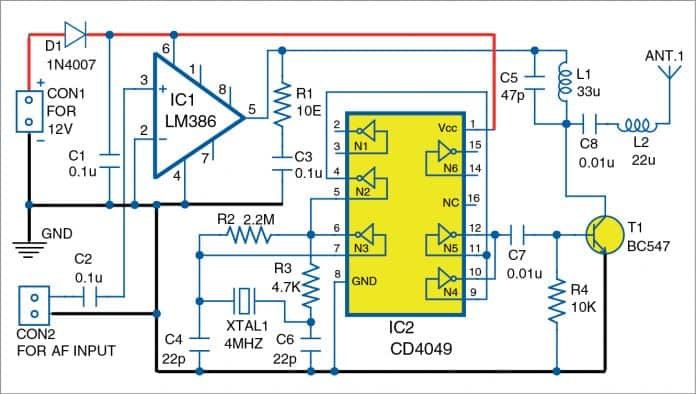
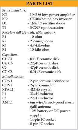
It is assembled around LM386 (IC1), CD4049 (IC2), and transistor BC547 (T1).
- The IC CD4049 is a hex inverter that has six inverter gates (Not gates) of which only four are used in this circuit.
- As demonstrated in the electronic schematic, the inverter gate between pin numbers 7 and 6 is used as a crystal-controlled oscillator.
- Then the output of the oscillator is given to the inverter gate between pin numbers 5 and 4, which is used as a buffer.
- The buffer’s output goes to two inverter gates between pin numbers 9 and 10 and 11 and 12 (connected in parallel).
- The yield of these gates goes to transistor T1, which is employed as a modulator and a class C amplifier as well.
- This method of modulation used here is different from the modulation techniques used in transmitter circuits and is known as power conversion.
- If a class C device amplifying one frequency has its input power varied at a second frequency, the output is modulated at the second frequency.
IC LM386 in the circuit is used as an audio-frequency amplifier. The output of this amplifier goes straight to the collector of transistor T1 through the tuned circuit composed of capacitor C5 and inductor L1.
Noted that the output of LM386 goes directly to the transistor and not through a capacitor (Similar as, when the IC is used as an audio frequency amplifier to drive a loudspeaker).
Power to the transistor is varied at an audio frequency and the amplitude modulated signal is obtained at its collector (As the DC voltage at the collector of the transistor should be half the power supply voltage under no-signal conditions).
The profit of this method of modulation is that the output power can be easily enhanced by replacing the audio frequency amplifier with a higher power amplifier and replacing the transistor with one capable of handling more power.
The output of IC2 is a square wave (According to Fourier analysis, a square wave consists of infinite series of sine waves of harmonics of the frequency of the square wave). The tuned circuit consisting of a capacitor C5 and inductor L1 is designed to select only the fundamental frequency; thus, the output is a sine wave of 4MHz frequency with the values of C5 and L1 selected for the circuit.
Here, L1 has some internal capacitance also thereby C5 may be replaced by a preset of 47pF as the resonance may occur at a capacitance lower than 47pF with the preset tuned to get utmost yield. The output is coupled to the antenna by capacitor C8 and inductor L2. (HELP: wire of six meters length can be used as the antenna or use a mesh for obtaining best results). Now connect the mesh with the transmitter by using a 1.5-meter long wire.
The audio source used for testing was a ‘Vire’ brand USB player. Excellent signals were received by using a Tecsun PL-390 radio receiver up to 500 meters away. If the audio source has a weak output, a 10µF capacitor can be connected between pins 1 and 8 of LM386. If the audio source has a strong output, it can be connected through a potentiometer to IC1.
The frequency of the oscillator can be changed by changing the crystal. An alternate method is to change L1 and C5 so that they form a tuned circuit that is tuned to the first harmonic.
Construction & Testing –
The PCB Layout and connections –
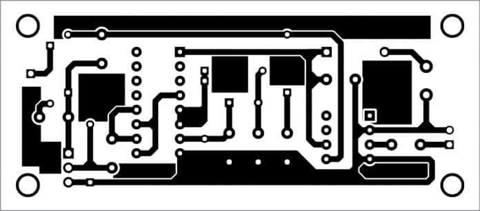
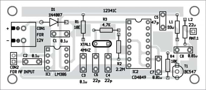
After wiring, connect the 12V DC power supply across CON1. Connect the audio output from your MP3 player, mobile phone, or laptop to the input of your transmitter across the CON2 connector. You are now ready to transmit and receive the signals in a shortwave radio up to 500 meters away.


