

Hey Freaks, Welcome again. Here we are back with another cool electronics project, Electronic Mosquito Repellent. The most optimum and easy solution for mosquito repellent is building a simple electronic device with minimum components which produce the output to repel the mosquitoes. In simple words, this project is going to describe how to make a simple mosquito repellent circuit?
Also Read: Heart Rate Monitor Using Arduino
Mosquito repellent products such as coils, liquid vaporizers, creams are mainly used. However, these mosquito repellents can cause harm to humans. The mosquito repellent creams and lotions can affects the skin and creates allergic reactions.
Principle of Electronic Mosquito Repellent Circuit:
We all know that, the humans can hear sound of range from 20 Hz to 20 kHz frequency. The frequency of sound above 20 kHz is ultrasonic sound. And, the various animals like cats, dogs, insects, mosquitoes are able to hear this frequency of ultrasonic sound.
Usually the male mosquitoes transmits the ultrasound and female mosquitoes received it. The ultrasound creates a stress on the antennae of the mosquitoes which makes them repels away.
In simple words, a simple electronic mosquito repellent circuit is designed which produces the ultrasound frequency of 20 kHz to 38 kHz range, and repels away the mosquitoes.
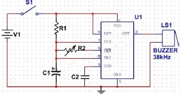
Circuit Diagram of Electronic Mosquito Repellent:
Components Required for Electronic Mosquito Repellent:
- 555 Timer
- The ceramic capacitor of 0.01 micro Farad
- Electrolyte capacitor of 0.01 micro Farad
- A resistor of 760 Ohms
- A resistor of 1.5 K
- Piezo buzzer
- An SPST switch
- A 5V battery
555 Timer IC is the most common form of Astable multivibrator, it is an 8 pin IC.
- Pin1 – Ground pin, directly connected to the -ve terminal of the battery.
- Pin2- Trigger Pin, an active low pin. When the signal at this pin is less than one-third of the voltage supply. The timer is triggered. This pin is connected directly to pin no.6, for astable operation.
- Pin 3 – It is the output pin.
- Pin 4 – It is the reset pin, an active low pin usually connected to the +ve terminal of the battery.
- Pin 5 – It is the control pin and is seldom used. For safety purposes, this pin is connected to the ground through a ceramic capacitor of 0.01microFarad.
- Pin 6 – It is the threshold pin. The timer output is back to its stable state when the voltage is greater than or equal to 2/3 of the voltage supply. This pin is shorted to pin 2 and connected to pin 7 using a resistorFor astable operation,
- Pin 7 –This pin provides the discharge path for the capacitor.
Also Read: Bidirectional Visitor Counter
Circuit Design of Electronic Mosquito Repellent:
The basic operation of this electronic mosquito repellent is to produce Ultrasound by using buzzer, which is driven by an Oscillator circuit. The 555 timer astable multivibrator circuit is used as an oscillator circuit.
The frequency of output signal produced by 555 timer IC is given by –
F = 1.44((Ra+Rb2)C)
where,
- Ra is the value of the resistor between pin 7 & Vcc.
- Rb is the value of the resistor between pins 7 & 6.
- C is the value of the capacitor between pin 6 & ground.
C = 0.01 microFarad
F = 38 kHz
Let D be the Duty Cycle,
D = 60%
Ra = 1.44(2D-1)/(F*C)
Rb=1.44(1-D)/(F*C)
Substituting values of C, D & F
Ra = 0.758 K Ohms
Rb = 1.52 K Ohms
Here we used used a Resistor of 760 ohms and another resistor of 1.5 Kohms and a potentiometer of 1.5 K.
Circuit Operation of Electronic Mosquito Repellent :
- The 555 timer IC gets the power supply on closing the switch.
- Initially, the voltage of the capacitor will be zero hence, the voltage at the threshold & trigger pin will be zero.
Also Visit: Latest Jobs, Interships & Off-Campus drives
- As the charging of capacitor happens through Ra & Rb resistors, at a certain point the capacitor voltage is greater than the voltage at threshold pin. This causes a change in timer output.
- Through the resistor Rb the capacitor starts discharging and continues so until the output voltage is back to the original.
- Thus the output signal with a frequency of 38 kHz is an oscillating signal.
- The output of the astable multivibrator circuit drives a 38 kHz piezo buzzer and produces ultrasound in repetitions.
- The output frequency varies with the variation by varying the value of the potentiometer.
The Electronic Mosquito Repellent circuit can also be used as other Insect repellents by changing the values of resistors and capacitors.
For more electronics projects visit our website regularly, and don’t forget to join our social media groups for the latest updates of jobs, internships & projects.


