

Hey freaks, Here we are back with another awesome Arduino project. In this project we have made a Color Detector Using Arduino.
A Color Detector or Sensor is basically a device that senses or detects colors. A color detector or sensor uses emitting light and then analyzes the light reflected from the object to determine the color.
Also Read: Heart Rate Monitor Using Arduino
The Color Detector Using Arduino will give an accurate color of the object. There are various applications of the color detectors such as sorting objects by color, printer color enhancement, etc.
We have designed a simple Arduino project, i.e Color Detector Using Arduino, which has the ability to detect different colors. In this color detector, we have used TCS3200 color sensors for detecting colors.
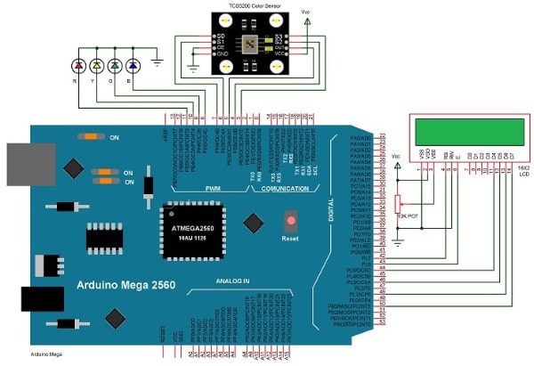
Circuit Diagram of Color Detector Using Arduino:
Required Components :
| Components | Buy From Amazon |
|---|---|
| Arduino Mega | Buy Now |
| TCS3200 Color Sensor Module | Buy Now |
| 16 x 2 LCD Display | Buy Now |
| Breadboard & Wires | Buy Now |
Working of Color Detector Using Arduino:
The Color sensor module TCS3200 has RGB + Clear Sensor along with 4 white LEDs embedded on its board. The module has an 8 x 8 array of photodiodes, 16 for each Red filters, Blue filters, Green filters, and Clear (no filter).
Also Read: Electronic Mosquito Repellent
The color sensor module TCS3200 is used which senses the color in its surroundings. The intensity of each of the colors is represented as frequency.
- In Arduino, by applying HIGH to S0 & S1 pins of the color sensor we have fixed the output frequency scale to 100%.
- To select the type of photodiode i.e. red, green, or blue S2 & S3 pin on the color sensor is used.
- The PULSEIN feature of the Arduino is activated on the pin connected with the output of the Color Sensor, whenever any particular Photodiode is selected.
- The above process is repeated for all three photodiodes of red, blue & green.
- By using the PULSEIN feature, the frequency in all the cases is measured and displayed on the Serial Terminal.
- This information is used to identify the color placed. Lights up the corresponding LED and displays its color on LCD.
Also Visit: Latest Jobs, Interships & Off-Campus drives
Program Code for Arduino:
*Arduino Mega*/

#include<LiquidCrystal.h>
LiquidCrystal lcd(42,43,44,46,48,50);

const int S0 = 7;
const int S1 = 6;
const int outPut= 5;
const int S2 = 4;
const int S3 = 3;


unsigned int frequency = 0;

void setup()
{

Serial.begin(9600);

pinMode(S0, OUTPUT);
pinMode(S1, OUTPUT);
pinMode(S2, OUTPUT);
pinMode(S3, OUTPUT);

pinMode(OutPut, INPUT);

digitalWrite(S0,HIGH);
digitalWrite(S1,HIGH);
}
void loop()
{
Serial.print("R=");
digitalWrite(S2,LOW);
digitalWrite(S3,LOW);
frequency = pulseIn(outPut, LOW);
Serial.print(frequency);
Serial.print("\t");

delay(500);

Serial.print("B=");
digitalWrite(S2,LOW);
digitalWrite(S3,HIGH);
frequency = pulseIn(outPut, LOW);
Serial.print(frequency);
Serial.print("\t");

delay(500);

Serial.print("G=");
digitalWrite(S2,HIGH);
digitalWrite(S3,HIGH);
frequency = pulseIn(outPut, LOW);
Serial.print(frequency);
Serial.print("\t");
delay(500);

Serial.print("\n");
}
For more electronics projects visit our website regularly and don’t forget to join our social media groups for the latest updates of jobs, internships & projects.


