
-min")
About the Monitoring of Water Level Project:
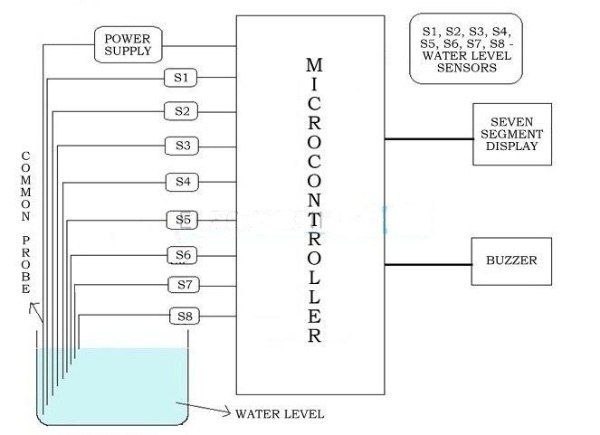
The monitoring of water level indicator is done by a system to detect and indicate the level of water in an water tank or any of water container. The sensing is performed here using a set of nine probes which are fixed at nine multiple levels on the water tank walls (with probe 1 to probe 9 are placed in decreasing order of height, common probe or a supply carrying probe is placed at the base of the water container or water tank). The level 8 indicates the ‘max water level’ condition while level 0 ‘min water level’ condition.
When the level of water is below the minimum detectable level (MDL), our display( i.e, seven segment display) is configured to display the digit 0, indicating that tank is in min water level condition, while when the water level reaches level 1 (but is not touching level 2) then connection gets completed between the probes (because of the conducting medium as water) and the base voltage of transistor increases.
This results in the base emitter junction of the transistor to get forward biased, this switches transistor to conduction mode from cut-off, thus PIN (B7) of microcontroller is pulled to ground connection and hence, the corresponding digit displayed is 1 in our seven segment display.
The above processes applies to the detection of other levels also. When the tank is filled completely, all input pins of microcontroller become low. This causes the display to show max warning and also here in this case a buzzer sound is given, thereby indicating a ‘max water’ condition.
Mostly water level indicators available are designed to indicate and detect only one level. The Water Level Indicator implanted here can indicate and detect up to nine such levels and in addition the microcontroller displays the level number of water on a seven segment display.
Also Read: Wireless AC light Dimmer Using Arduino: Hand Gesture based
So, our circuit not only warn a person that the tank of water has been filled up to certain mark, but also shows that the water level has drop below the minimum detectable level. This circuit has too many application such as the water cooler tank where there is a danger of motor damage when there is low water level also in the radiator used up also it can be used as indicator in fuel level indication.
In our project we tried to show the water level indication using eight transistors which conducts as level rises, additionally buzzer or bell is also added which will automatically sounds as soon as the water level becomes max or min, automatic buzzer start with the help of microcontroller that we use. With the application of this project we not only focus on the level of water on seven segment display but also shows the water full and empty condition using a buzzer sound and prevent overflow and shortage condition.
Water Level Alarming Project Features:
- Very easy to install.
- Negligible maintenance.
- Compact in design.
- The Automatic controller ensures no overflows or dry condition or empty tank condition.
- It saves electricity and water.
- Prevent seepage of roofs and walls due to overflow in tanks.
- Fully automatic, no need to monitor manually.
- Consume energy in very less amount which make this ideal for continuous operation.
- It provides you the power to decide by yourself different water levels for operations of pump or motors.
- Shows accurate indication of water levels in your tank.
Monitoring of Water Level Indicator Project Block Diagram:
CODE FOR PROJECT
How to Design Water Level Monitoring Project using AVR Microcontroller:
- A 5v power supply is given to the microcontroller along with the rest of the circuit from a battery.
- The tank contains 9 conductive type sensors used into it and 8 out of 9 wires of sensors are connected to transistors and the 9 one is connected to positive 5v supply.
- The aim of using a transistor is that it acts as inverter (i.e. in ON state condition gives low voltage output and in OFF state gives high voltage output), outputs of all transistors are connected to PORTB of microcontroller.
- Seven segment display we are using is connected to PORTD. It is connected in common cathode mode.
- The 7th level is not only shown on seven segment display but also notified with non continious buzzer sound.
- Output for the 8th level (i.e. tank full condition) is not even only shown in seven segmented display but also notified with a continuous buzzer sound.
Monitoring Water Level Indicator Circuit Diagram:
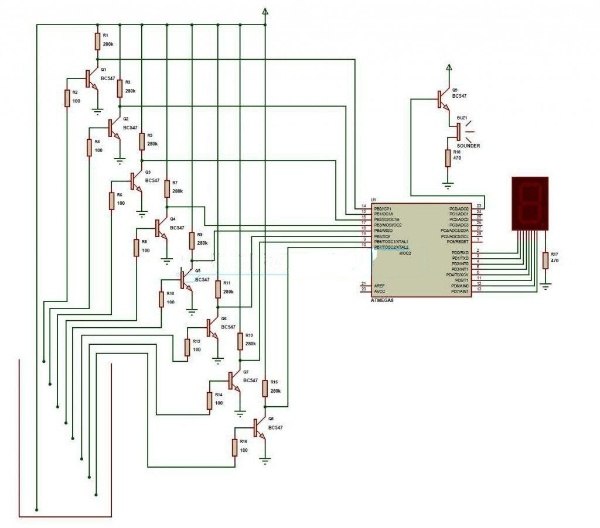
How Our Project Circuit Works:
The operation of our project is very simple way and can be understood easily. In our project “water level monitoring” there are 3 main cases:
- There is empty source tank.
- Intermediate level i.e. between 3rd to 7th level.
- There is overflow of water available in the source tank.
Also Visit: Latest Jobs, Interships & Off-Campus drives
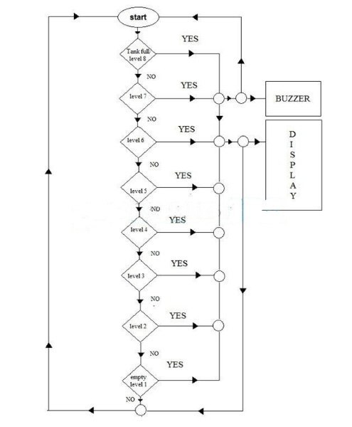
Water Level Indicator Project Working Flow Chart:
Also Read: Social Distancing Cap Using Arduino
The flow chart presented here gives a clear and easy understanding of the flow of the project. The process goes on as follows:
The microcontroller here checks for tank full condition, only if the condition is satisfied it indicates it on seven segment display unit and also produces sounds of buzzer if the condition does not satisfied then it checks again and this process continues and the corresponding level of water is indicated on the display unit.
Program code of Water Level Indicator: Click Here
For more electronics projects visit our website regularly, and don’t forget to join our social media groups for latest updates of jobs, internships & projects.


